

Ⅰ. Definition
The sandwich busway system—also known as the compact insulated busbar system—is a high-current transmission device utilized in modern power distribution systems as a substitute for traditional cables.
Its core design philosophy lies in eliminating the air gaps between conductors by tightly “compressing” the busbars of each phase together; hence, it is designated as “sandwich busway.”
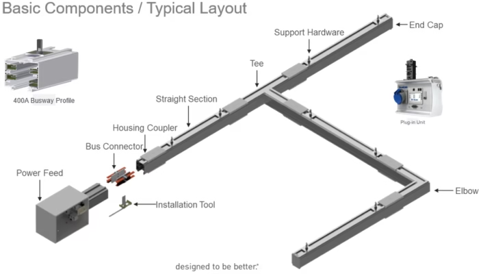
The main accessories include: connectors, end boxes, tap-off units, spring supports, hangers, support arms, transition bars, grounding wires, etc.
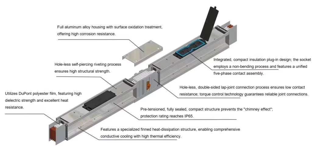
Conductor: Typically T2 high-purity electrolytic copper (purity >99.95%) or electrical-grade aluminum is used.
Insulation: Each conductor is wrapped in a high-performance insulating film (such as polyester film or PTFE), with an insulation class typically rated as Class B (130°C) or Class H (180°C).
Integral Pressing: Tightly bond together the insulated A, B, and C phases, as well as the neutral (N) and ground (PE) wires.
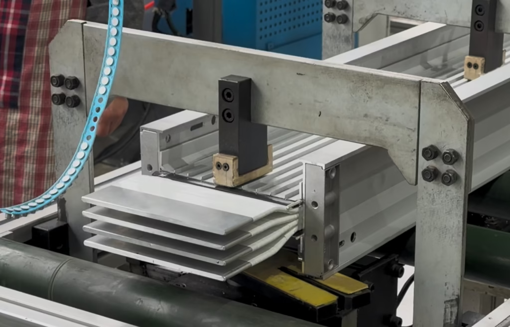
Housing: It is encased in an aluminum alloy or steel housing. This housing serves not only as a protective shield but also as a highly efficient heat sink.
Structural Features
- Suitable for large-span installation.
- The enclosure of the sandwich busway system is constructed using a rolling process; it features a compact size and an aesthetically pleasing appearance, while significantly enhancing long-term load-bearing capacity. It is capable of supporting a load of 60 kg at the center of a 6-meter span, with a deflection of less than 10 mm.
- Easy to install
- Connections featuring automatic compensation and single-bolt clamping terminals offer a high degree of adjustability, making the installation of sandwich bus duct systems highly convenient and flexible, thereby significantly reducing installation time.
- Safe and Reliable
- It adopts a split, air-insulated design, with safety clearances and phase-to-phase creepage distances significantly exceeding standard requirements.
- The internal insulation components are constructed from high-strength engineering plastics, thereby enhancing the dynamic and thermal stability of the sandwich bus duct system.
- The special structure of the connector prevents improper operation during installation.
- A protective safety baffle is installed at the socket outlet; a plug can be inserted into the receptacle only after this baffle has been opened. When the socket is not in use, the protective baffle can be securely sealed—typically using a wire seal—to prevent the ingress of dust or foreign objects, while simultaneously preventing power from being supplied via the meter’s input terminals. This design enhances the protective capabilities of the busway system, guards against accidental operation, and significantly improves the overall safety performance of the busway.
- Flexible Wiring
- The plug-in outlets of the sandwich busway system feature a modular design, allowing for the provision of numerous outlets throughout the entire system. This ensures that loads can be connected to the busbar units via the shortest possible path, eliminating the need to alter the busbar system when adding, relocating, or renovating workshop equipment.
- High Interchangeability
- The sandwich busway is designed with seven current ratings but utilizes only three enclosure sizes; consequently, when the system capacity is adjusted to an adjacent current rating, there is no need to replace the enclosure.
Ⅱ. Sandwich Busway Features
- Space Saving:Due to the absence of air gaps, its volume is significantly smaller than that of air-insulated busbars. In the narrow cable shafts of high-rise buildings or within data center equipment rooms, it enables substantial space savings.
- Superior Heat Dissipation: The heat generated by the conductor is directly conducted through the insulating layer to the metal casing, utilizing the entire surface area of the casing to dissipate heat into the air. This heat conduction efficiency is significantly higher than that of air convection.
- Low Voltage Drop: The compact structure endows the busbar with extremely low reactance. During high-current, long-distance power transmission, energy loss is minimized, resulting in more energy-efficient operation.
- Safety:Due to the absence of internal air spaces, it completely eliminates the “chimney effect.” In the event of a fire, flames and smoke are unable to spread rapidly through the interior of the busbar to other floors.
| Key Parameters | Typical Range / Performance |
|---|---|
| Rated Current | 400A — 6300A |
| Rated Voltage | AC 380V / 690V / 1000V |
| IP Rating | IP54 (standard) — IP66 (outdoor/High Standards) |
| Short-circuit | It features a compact structure and possesses exceptional resistance to electromagnetic repulsion forces. |
| Connection | Single-Bolt Connector (Shear-Head Bolt — Ensures Proper Torque) |
Ⅲ. Application Of Sandwich Busway
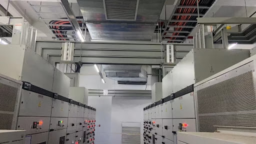
- High-rise buildings and commercial complexes represent the most classic application scenario for compact busbar systems.
- Vertical Risers: In the cable shafts of high-rise office buildings, hotels, or apartment complexes, busbars are installed vertically to transmit power from the underground distribution room to the various floors.
- Space-Saving: Sandwich busway feature an extremely small footprint, saving approximately 50% to 70% more space compared to cables with equivalent current-carrying capacity—thereby freeing up additional leasable area for developers.
- Data Centers
- Cabinet Row Power Distribution: A busway is installed horizontally above the cabinets, directly supplying power to each row of server cabinets via Tap-off Boxes.
- Hot-Swap Advantage: Plug-in units can be added or relocated without interrupting power, perfectly accommodating the requirements for frequent server expansion.
- Industrial Plants
- High-Power Equipment Supply: Provides stable, high-power electrical support for equipment such as large stamping presses, injection molding machines, and welding robots.
- Durability: The aluminum alloy housing not only facilitates rapid heat dissipation but also possesses exceptional mechanical strength, enabling it to withstand vibrations and environmental stresses within a factory setting.
- Infrastructure
- Airports and Subway Stations: These venues impose extremely stringent requirements regarding fire safety ratings. Since compact busbar systems lack internal air gaps—thereby eliminating the “chimney effect”—they do not serve as conduits for the propagation of smoke during a fire.
- Hospitals: Ensure a stable power supply with extremely low voltage drop in critical areas, such as operating rooms and ICUs.
- Transformer to Switchgear
- Rigid Connection: Sandwich busway are frequently used for the connection between the low-voltage side of a transformer and the incoming cabinet of a distribution switchgear (i.e., a “busbar bridge”).
- High Short-Circuit Strength: Capable of withstanding the immense electromagnetic repulsive forces generated by short-circuit currents at the transformer outlet.
Ⅳ. How To Install Sandwich Busway?
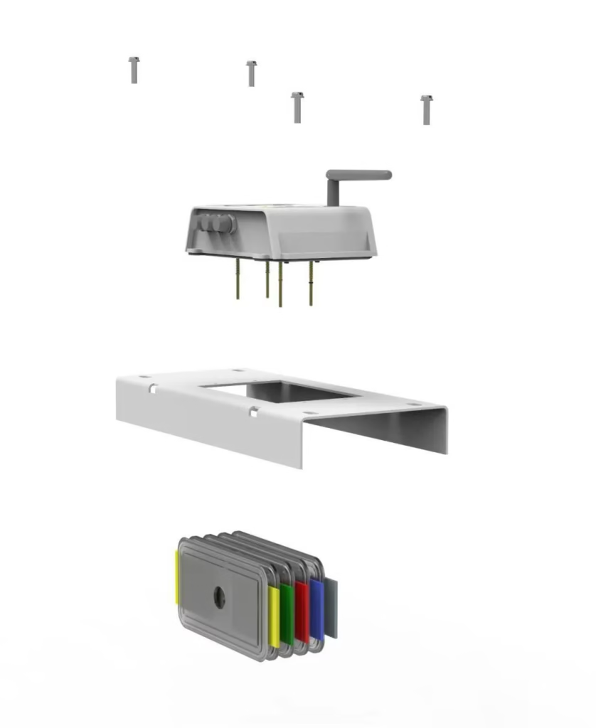
- Pre-installation
- Visual Inspection: Check the busbar enclosure for deformation and verify that the sealing strips are intact.
- Insulation Testing: Prior to installation, the insulation resistance of each busbar section must be measured using a 1000V megohmmeter.
- Bracket Installation: Install suspension brackets or horizontal brackets in accordance with the design drawings. For horizontal installations, the spacing between brackets typically does not exceed 1.5 m to 2 m.
- Visual Inspection: Check the busbar enclosure for deformation and verify that the sealing strips are intact.
- Joint Connection
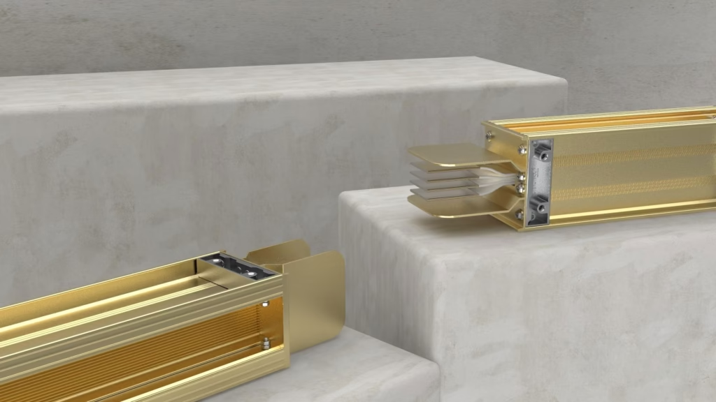
- Alignment and Connection: Align the connecting ends of the two busbar sections. Ensure that the phase sequence (A, B, C, N) is strictly identical. Sandwich busway systems typically feature a “misalignment-proof” design.
- Joint Kit: Insert the specialized connecting insert into the gap between the copper busbars of the two busbar sections.
- Torque Fastening: Sandwich busway systems typically utilize double-ended constant-torque bolts.(Procedure: Use a standard wrench to tighten the bolt until the outer bolt head automatically shears off. This indicates that the tightening torque has reached the preset standard (typically 70–80 N·m), thereby ensuring minimal contact resistance.)
- Alignment and Connection: Align the connecting ends of the two busbar sections. Ensure that the phase sequence (A, B, C, N) is strictly identical. Sandwich busway systems typically feature a “misalignment-proof” design.
- Housing & Sealing
- Side Panel Installation: Install cover plates at the connection points to ensure the continuity of the enclosure; this is critical to the grounding (PE) performance of the entire busbar system.
- Waterproofing: For busbars with an IP54 or higher protection rating, sealant must be applied or sealing gaskets installed at the connections.
- Side Panel Installation: Install cover plates at the connection points to ensure the continuity of the enclosure; this is critical to the grounding (PE) performance of the entire busbar system.
- Vertical Riser Installation
- Spring Supports: Specialized spring supports must be used. They are capable of absorbing stresses resulting from building settlement or the thermal expansion and contraction of the busbar.
- Floor Sealing: After the busbar passes through the floor slab, it must be sealed using firestop putty or firestop bags to prevent the spread of fire.
- Spring Supports: Specialized spring supports must be used. They are capable of absorbing stresses resulting from building settlement or the thermal expansion and contraction of the busbar.
- Commissioning
- Secondary Insulation Testing: Upon completion of the entire line installation, a comprehensive insulation test must be conducted once again prior to energization.
- Phase Verification: Check whether the phase sequence at the starting point (transformer side) corresponds one-to-one with that at the ending point (switchgear side).
- No-load Operation: First, power on the unit under no-load conditions for 24 hours, and observe for any abnormal heat generation or noise.
- Secondary Insulation Testing: Upon completion of the entire line installation, a comprehensive insulation test must be conducted once again prior to energization.
As an efficient and reliable power transmission device, sandwich bus duct systems are widely utilized in a diverse range of industrial and civil buildings. However, given the vast array of bus duct products available on the market—and their varying levels of quality—determining how to distinguish between superior and inferior products has become a critical issue.
- Conductor Materials
- The conductor material constitutes the core component of a sandwich busway system; its quality directly impacts the system’s overall performance. High-quality sandwich busway systems typically utilize high-purity copper or aluminum as conductor materials, as these materials possess excellent electrical conductivity and mechanical properties. For instance, copper conductors exhibit low resistivity, which effectively minimizes power loss and enhances transmission efficiency. When making a selection, one should review the product’s technical specifications to verify the specifications and purity of the conductor material.
- Insulating Materials
- The function of insulating materials is to prevent current leakage and ensure electrical safety. High-quality sandwich busway systems utilize high-performance insulating materials, such as polyester film or mica tape. These materials possess excellent insulating properties and heat resistance, enabling them to maintain stability even in high-temperature environments. When making a purchase, one can assess the quality of the product by reviewing its insulating material certifications and test reports.
- Structural Design
- The structural design of a sandwich busway system is critical to its performance. A well-engineered structural design enhances heat dissipation and increases current-carrying capacity. For instance, in a sandwich busway system, the conductors—as well as the conductors and the enclosure—are in close contact; this structural arrangement enables the electrical busway to dissipate heat more effectively than traditional cables, thereby achieving a higher current-carrying capacity. Furthermore, tapping units can be strategically positioned based on the specific locations of loads at the user’s project site, and multiple current tapping interface modules can be pre-reserved at various points along the system, allowing users to easily adjust or expand their equipment loads at any time.
- Protection Class
- The protection rating serves as a crucial indicator for assessing the dust and water resistance capabilities of sandwich busway systems. The protection rating of a sandwich busway system varies depending on its specific operating environment. Generally, sandwich busway systems installed indoors should have a protection rating of no less than IP54. When making a purchase, it is essential to select an appropriate protection rating based on the actual operating environment to ensure the safe and reliable operation of the equipment.
- Certification And Testing
- Product certification and testing serve as crucial benchmarks for assessing quality. Legitimate sandwich busway systems typically undergo a series of certifications and tests—such as CQC, CE, and RoHS—to ensure compliance with relevant quality standards and environmental regulations. When making a purchase, buyers may request that the supplier provide product certification certificates and test reports to verify the product’s quality and safety.
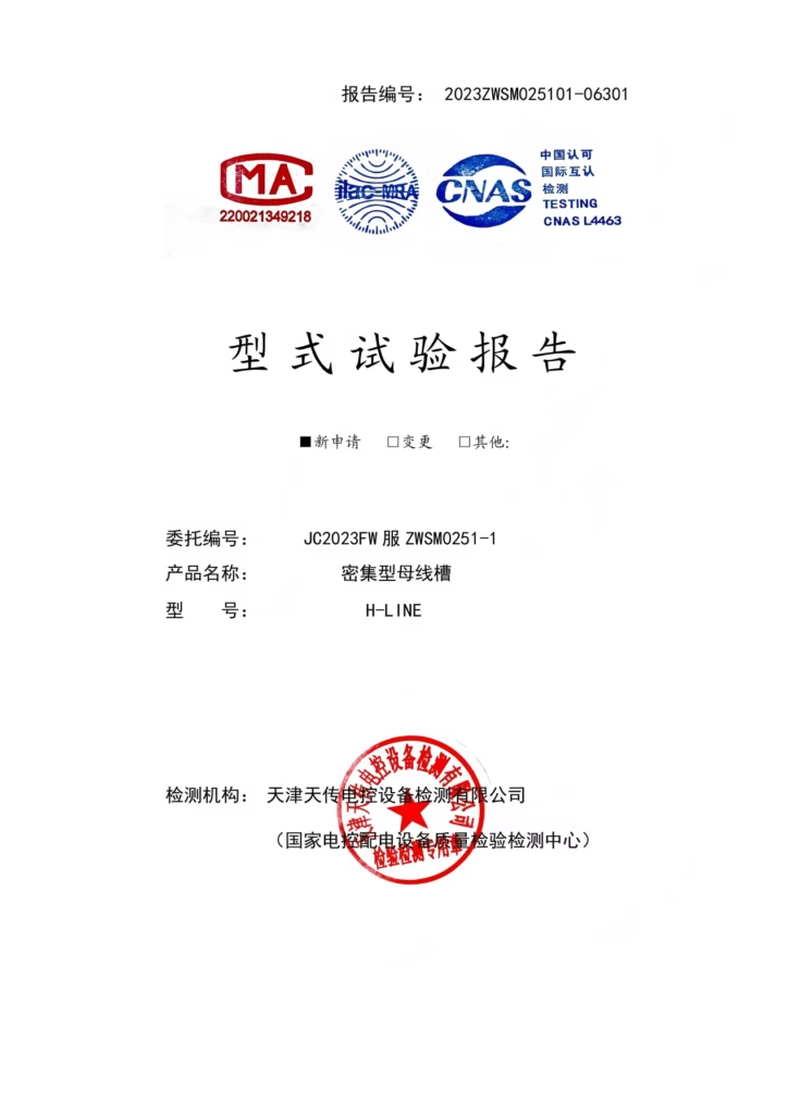
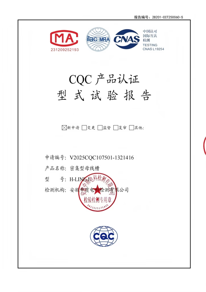
Assessing the quality of a sandwich busway system requires a comprehensive evaluation across multiple aspects. By focusing on factors such as conductor materials, insulation materials, structural design, protection ratings, certifications and testing, and after-sales service, you can effectively select a compact busbar product that offers reliable quality and superior performance—thereby ensuring stable and secure power transmission for your electrical system.
Ⅵ. Differences Between Compact Bus Ducts and Air-Insulated Bus Ducts
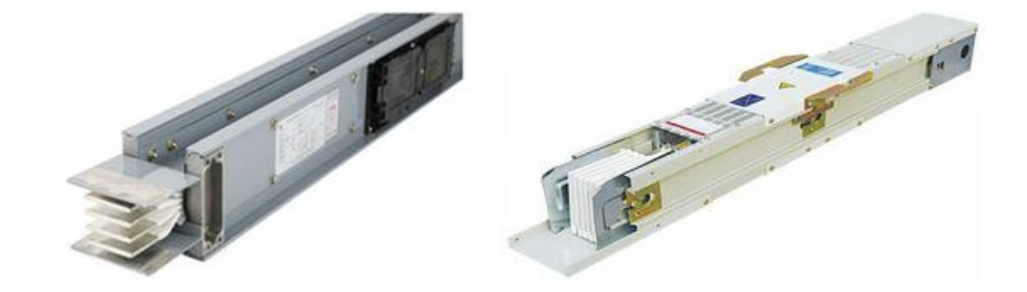
Sandwich Type: Compact Type: The bare busbars are covered with insulating material and placed in close contact with the enclosure.
Air-Insulated Type: The busbars are supported within the enclosure by insulating spacers, relying on air as the insulating medium.
| Air-Insulated Busway | Sandwich Busway | |
|---|---|---|
| Rated Current Value | Up to 3100A/4000A | Up to 6300A |
| Heat Dissipation Principle | Ventilation holes on the enclosure facilitate convection between the air inside the bus duct and the external environment, thereby dissipating the heat generated by the electrical busways; however, the heat dissipation efficiency is low. | Metals possess high thermal conductivity, enabling direct, comprehensive heat dissipation through the casing, resulting in high cooling efficiency. |
| Temperature Rise | Due to low heat dissipation efficiency, the temperature rise is relatively high. | It features high heat dissipation efficiency, resulting in a low temperature rise. |
| Protection Class | If a higher degree of protection is required, the busbar capacity must be derated (from 3200A to 2520A). | Rated up to IP66. (Since the housing features no ventilation holes, dust and water cannot enter.) |
| Resistance to Environmental Pollution | Poor, External dust and particulates can enter through the heat dissipation vents, contaminating the interior of the busbar. | Robust and effective at preventing the ingress of dust and impurities. Suitable for use in heavily contaminated work environments, such as those found in the chemical, steel, and wood processing industries. |
| Dynamic Stability and Mechanical Strength | The electrodynamic forces acting on the busbars are exerted upon the insulating supports (20–60 kA for 1 second). | Due to the tight contact between the copper busbars, the electrodynamic forces acting on the busbar system are distributed uniformly across the entire length of the copper bars and the enclosure; consequently, the system is capable of withstanding high short-circuit currents (ranging from 40 to 100 kA for a duration of 1 second). |
| Insulating Medium | Air | Organic materials are required to be thin, possess high dielectric strength, and exhibit good thermal resistance. |
| Resistance | It is relatively high, as resistance depends not only on the purity of the copper busbar and contact resistance but is also related to the conductor temperature (the higher the temperature, the greater the resistance). | Resistance is low due to low temperature rise. Line voltage drop is minimal, and losses are low. |
| Installation Space | Requires a large amount of space. | Minimal space requirements (30%), compact structure. |
| Installation Time | Busbars are large and heavy (30%), making installation slow and inconvenient. | The lightweight design, combined with single-joint screws, ensures convenient and reliable installation. |
| Capacity Reduction | For inclined or vertical installations, derating factors must be taken into account, as improper positioning can impede airflow and compromise heat dissipation. | No Derating Required |
| Chimney Effect | The internal air gaps within vertically rising busbars create a chimney effect in the event of a fire within the building. | High-density design, no chimney effect. |
| Other | A humid and rainy climate can easily cause electrical short circuits. | Compact design—does not interfere. |
Ⅶ. Why Choose HD Electrical Busway?
- Premium Raw Materials
- High-Purity Electrolytic Copper: We utilize only T2 electrolytic copper with a purity level of up to 99.95%. This translates to lower electrical resistance, reduced voltage drop, and minimized thermal energy loss.
- Full-Length Tin-Plating Process: The entire length of the conductor undergoes automated tin-plating treatment, which not only enhances conductivity but also ensures exceptional corrosion resistance in humid or high-salt-mist environments (such as coastal regions).

- State-of-the-Art CNC Manufacturing
- Siemens PLC Control: Our production lines utilize advanced CNC busbar processing machines. Punching precision (Click to view CNC busbar punching equipment) is controlled within ±0.1 mm, ensuring that every busbar section achieves “perfect alignment” during on-site assembly.

-
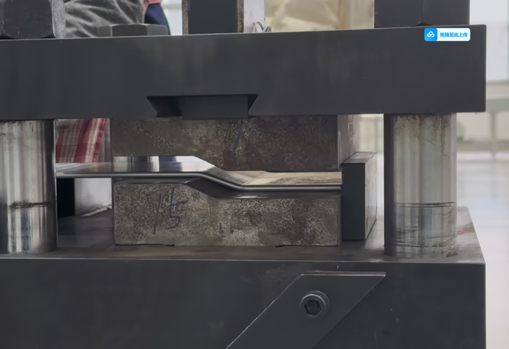
- Non-Destructive Bending Technology (Click to view CNC Busbar Bending Equipment): Automated CNC bending ensures precise and smooth bend radii, preventing any compression of the internal insulation layer; this effectively eliminates, at the source, the risk of insulation breakdown caused by processing-induced stress.
- Non-Destructive Bending Technology (Click to view CNC Busbar Bending Equipment): Automated CNC bending ensures precise and smooth bend radii, preventing any compression of the internal insulation layer; this effectively eliminates, at the source, the risk of insulation breakdown caused by processing-induced stress.
- Military-Grade Insulation & Heat Dissipation
- Class H Insulation Rating: We employ a multi-layer polyester film for comprehensive encapsulation, achieving a temperature resistance rating of up to 180°C—far exceeding the industry standard Class B.
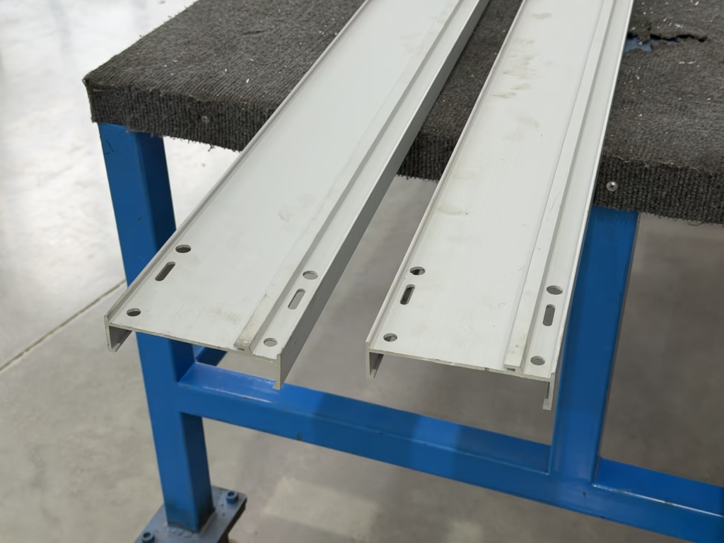
- High-Performance Aluminum Alloy Enclosure: Features a lightweight, high-strength aluminum alloy housing. It ensures zero magnetic loss and rapid heat dissipation, while the entire enclosure serves as a 100% capacity protective earth (PE) conductor, thereby enhancing safety.
- Class H Insulation Rating: We employ a multi-layer polyester film for comprehensive encapsulation, achieving a temperature resistance rating of up to 180°C—far exceeding the industry standard Class B.
- Advanced Jointing Technology
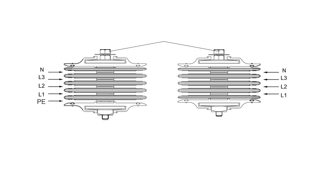
- Double-Headed Constant-Torque Bolt: On-site installation requires no specialized expertise. Simply tighten the bolt until the outer head shears off; this indicates that the pressure has reached the optimal standard (70–80 N·m), thereby completely eliminating potential human-induced safety hazards.
- Single-Bolt Connector: Features a compact design and supports compensation for thermal expansion and contraction, ensuring the connection remains securely fastened throughout its 30-year service life.
- Double-Headed Constant-Torque Bolt: On-site installation requires no specialized expertise. Simply tighten the bolt until the outer head shears off; this indicates that the pressure has reached the optimal standard (70–80 N·m), thereby completely eliminating potential human-induced safety hazards.
- Rigorous Testing & Certification
- Full Type Testing: Our products have successfully passed rigorous temperature rise tests, short-circuit strength tests, and ingress protection (IP) tests (up to IP66).
- 100% Factory Insulation Testing: Prior to packaging and export, every busbar section undergoes a 2000V withstand voltage test and insulation resistance measurement, accompanied by a dedicated test report.
- Full Type Testing: Our products have successfully passed rigorous temperature rise tests, short-circuit strength tests, and ingress protection (IP) tests (up to IP66).
- Global After-Sales & Support
- In-Depth BIM Integration: We can provide detailed 3D design development for your engineering projects, ensuring the optimal routing of busbars.
- Rapid Delivery: Our modular production model ensures that even large-volume orders can be shipped globally via sea freight within the shortest possible timeframe.
- In-Depth BIM Integration: We can provide detailed 3D design development for your engineering projects, ensuring the optimal routing of busbars.
Ⅷ. Sandwich Busway Maintenance
The Main Common Causes of Short Circuits in Sandwich Busway Systems
- Insulation Failure — The Primary Cause
- Physical Puncture: During the processing of conductors (copper or aluminum busbars), if punching, shearing, or bending operations result in the formation of burrs, these sharp metal protrusions may—over time and amidst the minute vibrations induced by alternating current—puncture the insulating layer.
- Excessive Compression: During the tightening of the joint kit, uneven bolt torque—or the subjection of the busbar to abnormal mechanical stress at a bend—can cause the insulation layer to thin or even rupture.
- Electrical Breakdown: The insulating material contains quality defects (such as micropores or bubbles), resulting in breakdown under prolonged high-voltage conditions.
- Physical Puncture: During the processing of conductors (copper or aluminum busbars), if punching, shearing, or bending operations result in the formation of burrs, these sharp metal protrusions may—over time and amidst the minute vibrations induced by alternating current—puncture the insulating layer.
- Loose Joints & Overheating
- Insufficient Torque: If double-ended constant-torque bolts are not utilized during installation—or if the bolts are not tightened sufficiently due to the workers’ lack of experience—it will result in excessive contact resistance at the connection point.
- Thermal Expansion and Contraction: When high currents flow through a copper busbar, it undergoes thermal expansion. If the connector lacks effective displacement compensation, prolonged mechanical reciprocating motion can lead to loosening of the contact surfaces, resulting in arcing; ultimately, this can burn through the insulation and cause a phase-to-phase short circuit.
- Insufficient Torque: If double-ended constant-torque bolts are not utilized during installation—or if the bolts are not tightened sufficiently due to the workers’ lack of experience—it will result in excessive contact resistance at the connection point.
- Environmental Ingress
- Condensation: When a busbar operates in an environment characterized by significant temperature differentials (such as a basement or a poorly climate-controlled facility), condensation forms on the inner surface of the enclosure, resulting in a drastic reduction in creepage distance.
- Conductive Dust: In industrial environments (such as cement plants or metal processing facilities), if conductive dust enters a tap-off opening, it can form a conductive bridge between phases, thereby triggering an arcing short circuit.
- Condensation: When a busbar operates in an environment characterized by significant temperature differentials (such as a basement or a poorly climate-controlled facility), condensation forms on the inner surface of the enclosure, resulting in a drastic reduction in creepage distance.
- Improper Installation
- Left-behind Foreign Objects: During the installation process, if metal shavings, gaskets, or small tools are left inside the busbar, the intense electromagnetic fields generated upon energization can cause them to shift, thereby triggering a short circuit.
- Phase Sequence Mismatch: This is a simple yet extremely dangerous error. If phases A, B, and C are incorrectly connected during assembly, energizing the system will immediately result in a severe phase-to-phase short circuit.
- Inadequate Sealing: For outdoor busbars or those with high protection ratings (IP54/IP66), if the sealing gaskets at the connections are not properly installed, rainwater ingress serves as a direct trigger for short circuits.
- Left-behind Foreign Objects: During the installation process, if metal shavings, gaskets, or small tools are left inside the busbar, the intense electromagnetic fields generated upon energization can cause them to shift, thereby triggering a short circuit.
- System Overload and Short-Circuit Current Surge
- Electrodynamic Repulsion Damage: When a short circuit occurs in a downstream load, the entire busbar system is subjected to an immense short-circuit current. The powerful, instantaneous electromagnetic repulsion generated by this event causes displacement of the internal conductors within the bus duct; if the supporting brackets or enclosure lack sufficient structural strength, this can lead to a collapse of the internal structure and trigger a secondary short circuit.
Methods for Handling Busbar Trunking Faults
- Preliminary Fault Diagnosis
- Visual Inspection: Check the housing for any signs of deformation, discoloration, or scorching. Pay particular attention to the connections at the joints and tap-off boxes.
- Temperature Monitoring: Conduct scans using an infrared thermal imager. If the temperature rise in a specific section is abnormally higher than in other sections (typically exceeding 60–70 K), it indicates the presence of a poor contact at that location.
- Insulation Resistance Test (IR Test): Use a 1000V/2500V megohmmeter.
- Phase-to-phase insulation: A-B, B-C, C-A.
- Relative insulation: A-PE, B-PE, C-PE, N-PE.
- Evaluation Criterion: The insulation resistance of busbars in operation shall be ≥ 0.5–20 MΩ (depending on ambient humidity).
- Common Troubleshooting Methods
- Connection Overheating
- Phenomenon: The casing at the connection point is overheating, and the gaskets on the connecting bolts have turned blue.
- Remedial Measures:
- De-energize and Lockout/Tagout (LOTO).
- Disconnect the connector and inspect the contact surfaces of the busbar for oxidation, blackening, or electrical pitting.
- Use fine sandpaper to sand away the oxide layer, then reapply electrical contact grease.
- Replace with new double-ended torque bolts to ensure the tightening pressure meets specifications.
- Connection Overheating
-
- Insulation Breakdown / Short Circuit
- Symptom: The circuit breaker trips, accompanied by a loud cracking sound or smoke.
- Remedial Measures:
- Locate the faulty section. Since sandwich busways are not repairable (due to their tightly laminated internal structure), the entire busbar section typically requires replacement.
- Check whether the ends of adjacent sections have been affected by the arc, and clean up any spattered metal debris.
- Recommendation: Analyze the cause of the short circuit (e.g., water leakage, puncture by burrs, or overload), resolve the issue at its root, and only then restore power.
- Insulation Breakdown / Short Circuit
-
- The casing is live.
- Symptom: A tingling sensation is felt when touching the casing.
- Remedial Measures:
- Check the earthing continuity of the entire circuit.
- Check whether the grounding jumper at the connector or the fasteners on the aluminum alloy housing are loose.
- Verify whether any wires inside the junction box have damaged insulation and are in contact with the metal enclosure.
- The casing is live.
- Standardized Procedure for Major Overhauls During Power Outages
- Power-off Verification: It must be ensured that the upstream switch has been disconnected, and that voltage verification and discharge procedures have been performed.
- Sectional Isolation: Isolate the suspected faulty busbar section from the system and measure its insulation independently.
- Cleaning and Dehumidification: Use dry compressed air to purge the connectors. If the decline in insulation is caused by moisture, an industrial hot air blower may be used for continuous drying.
- Calibration and Alignment: When replacing a section, ensure that any displacement caused by thermal expansion and contraction has been reset, thereby preventing the generation of shear stress resulting from forced alignment.
- Trial Run: Upon completion of repairs, power on the unit under no-load conditions for 24 hours, monitoring for temperature rise and abnormal sounds.